The last parts were delivered from ebay on the 3rd of march. This took a bit longer than usual as I managed to order during the chinese new year.
With all the parts at hand i decided to start building, while the paint on the frame dries I started working on the electronics.
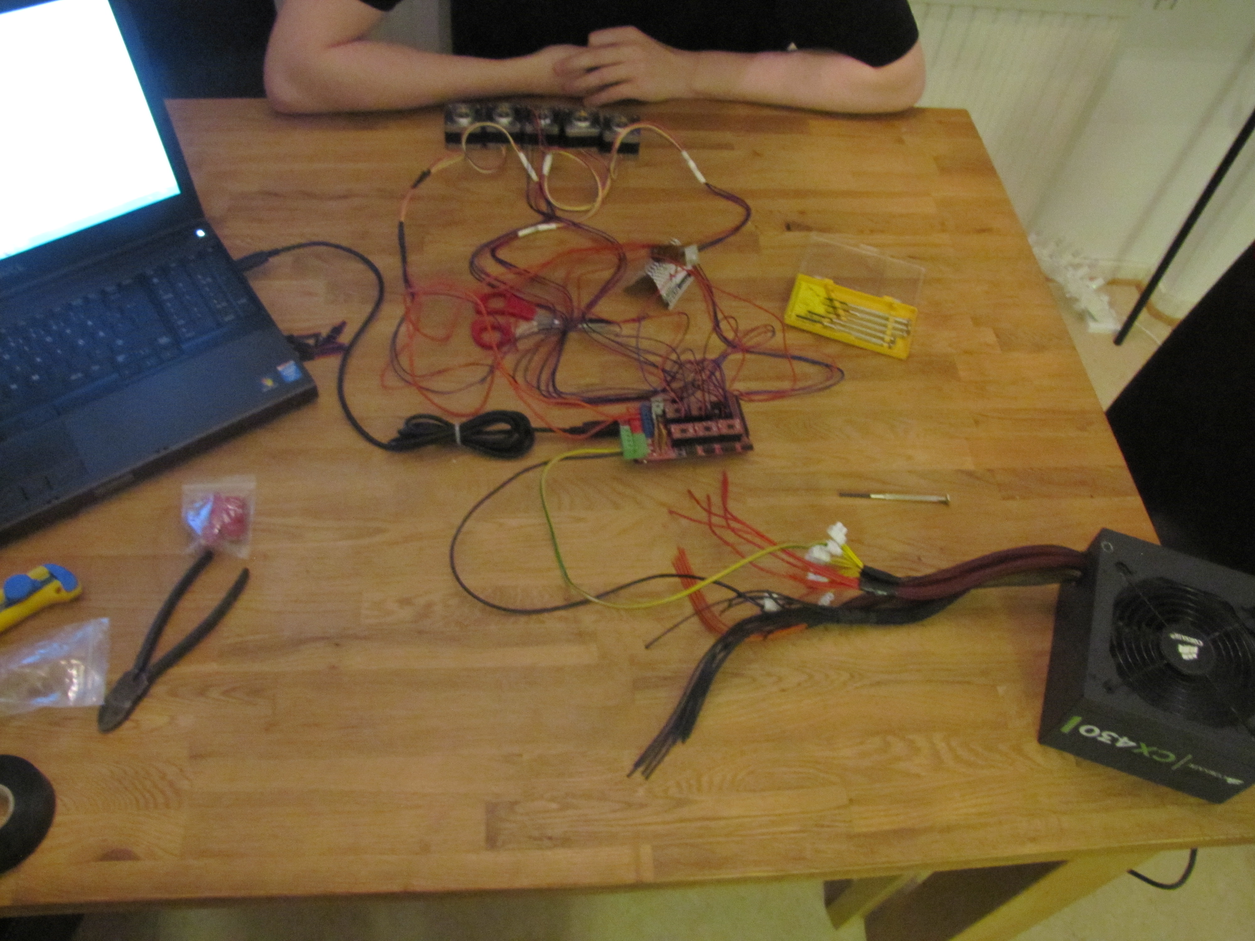
I converted a old Corsair cx430 to work with the printer. At 12v and 430W the supply can output about 35 amps which is more than enough.
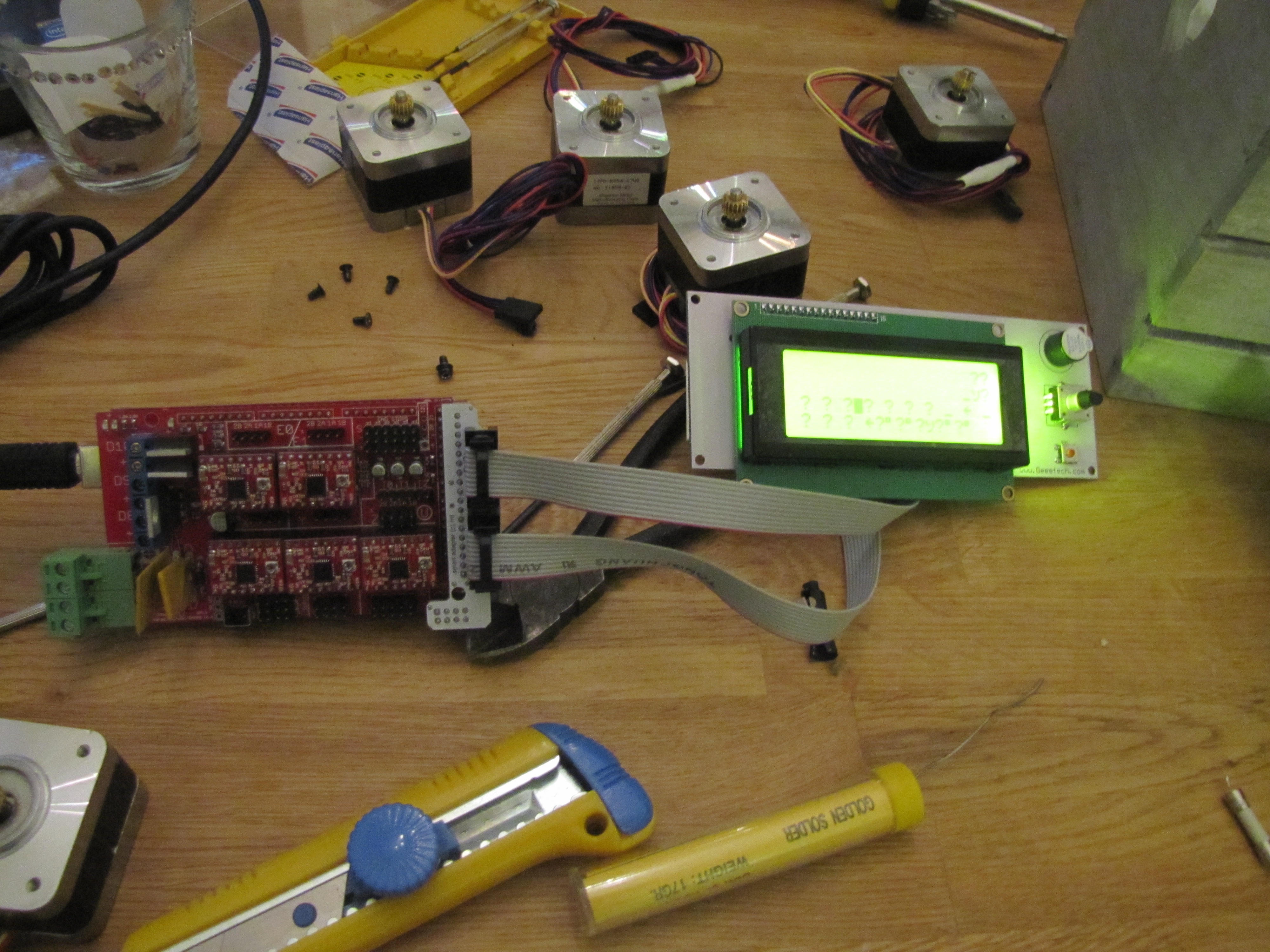
Here is a picture of the Mega 2560+RAMPS 1.4 with 5 stepper drivers mounted, 5 motors connected and the hotend connected.
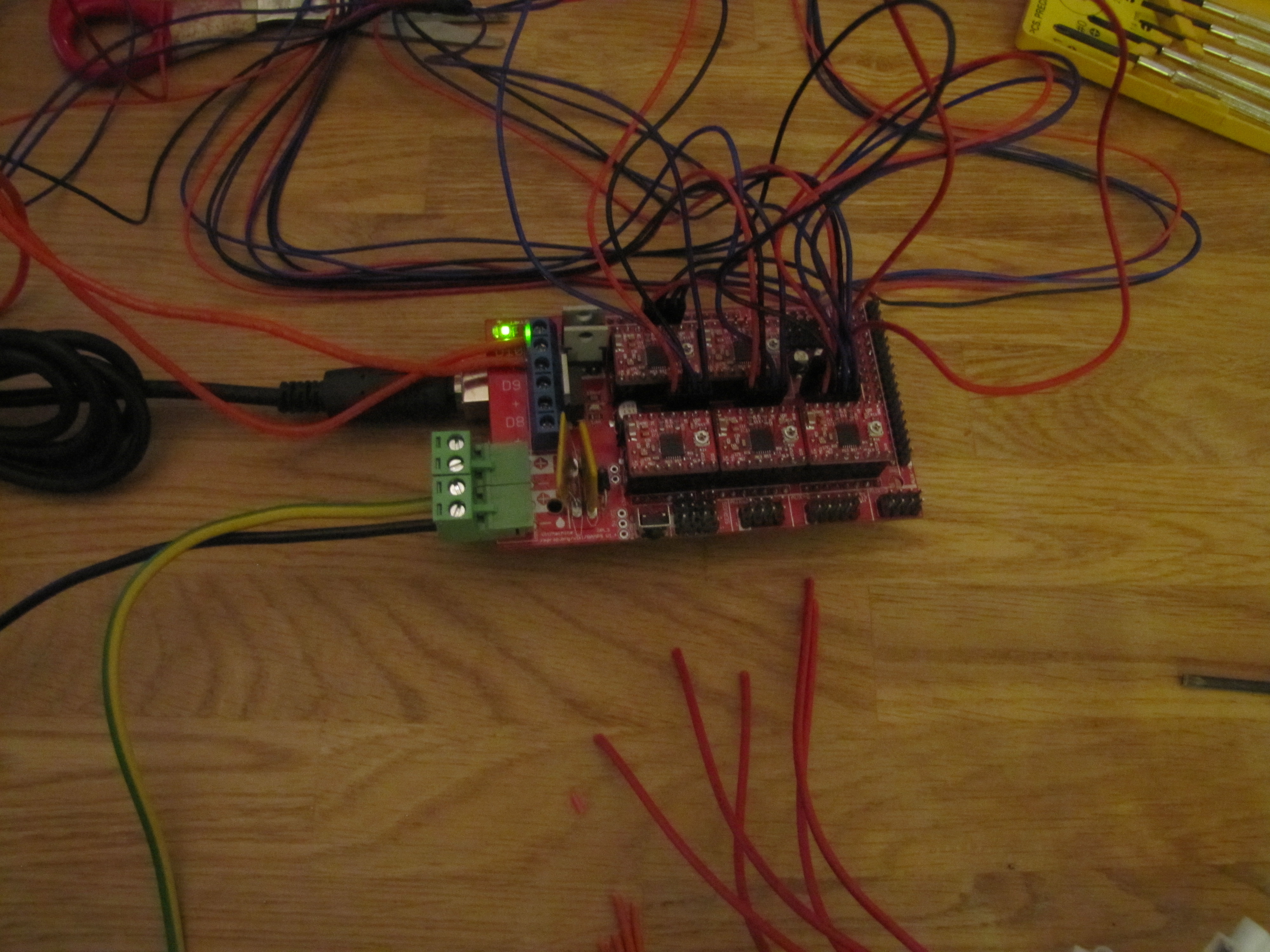
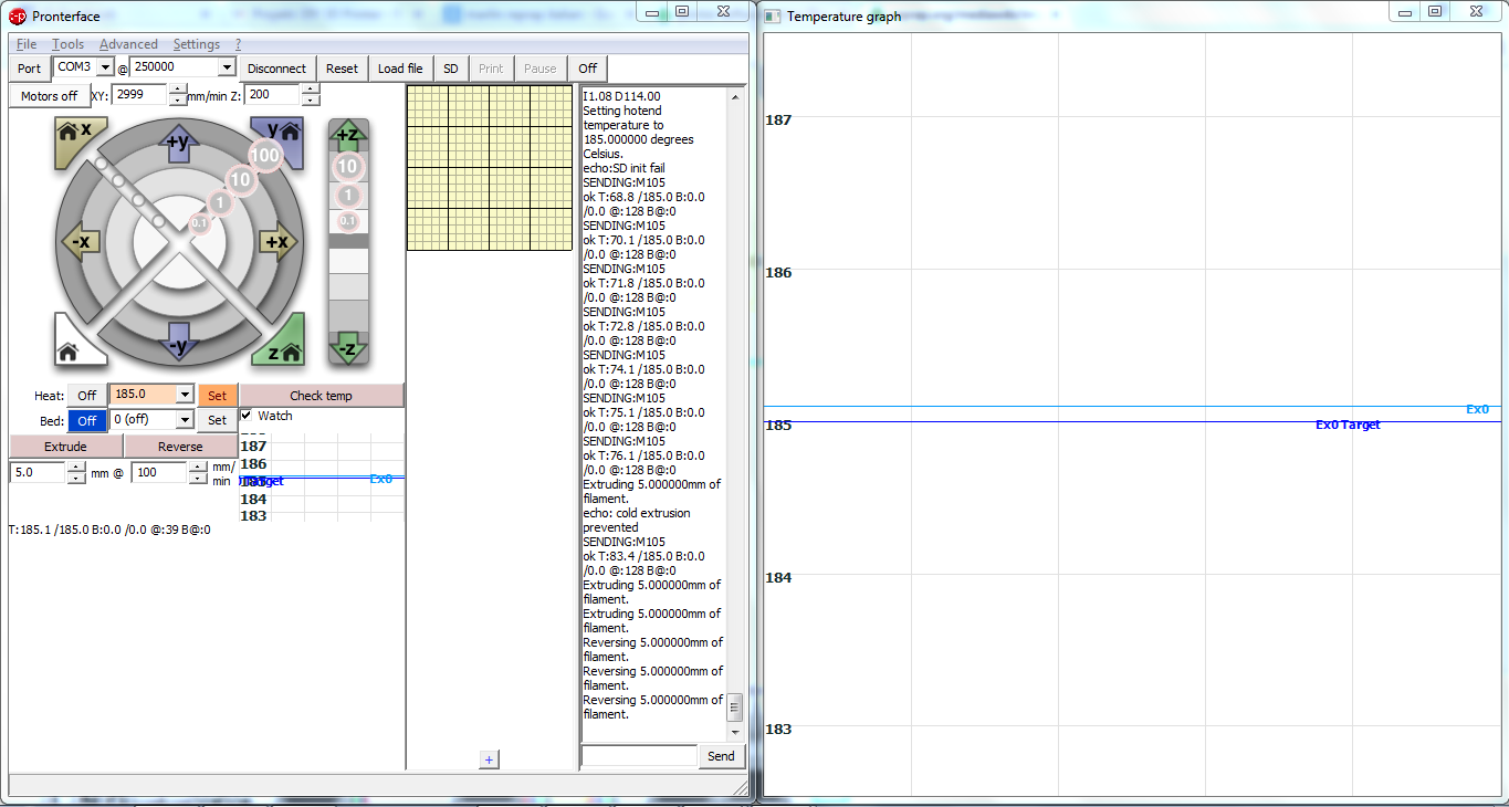
The firmware I’m using is Marlin. Marlin is a deviation on Sprinter and has LCD support amongst other improvements.
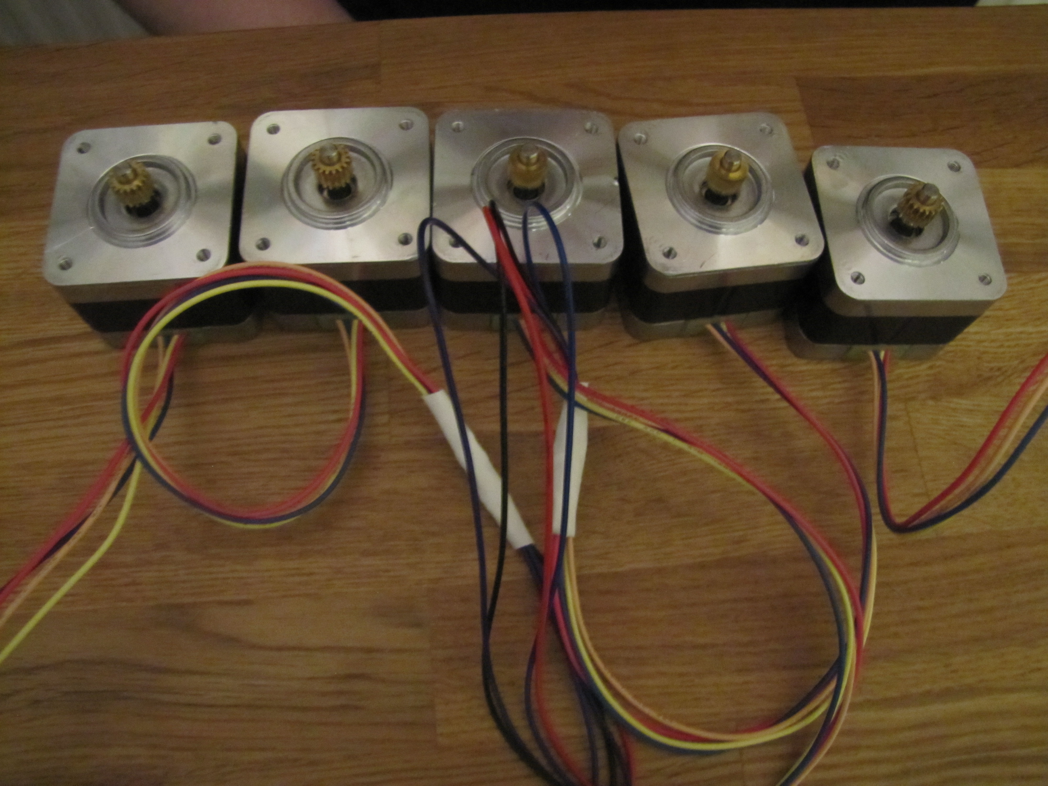
Image of the motors, both Z axises are running.
From left to right:
X axis, Y axis, 2x Z axis, Extruder motor.
When connecting the LCD I noticed something was off, the display shows garbage and nothing can be read from it.
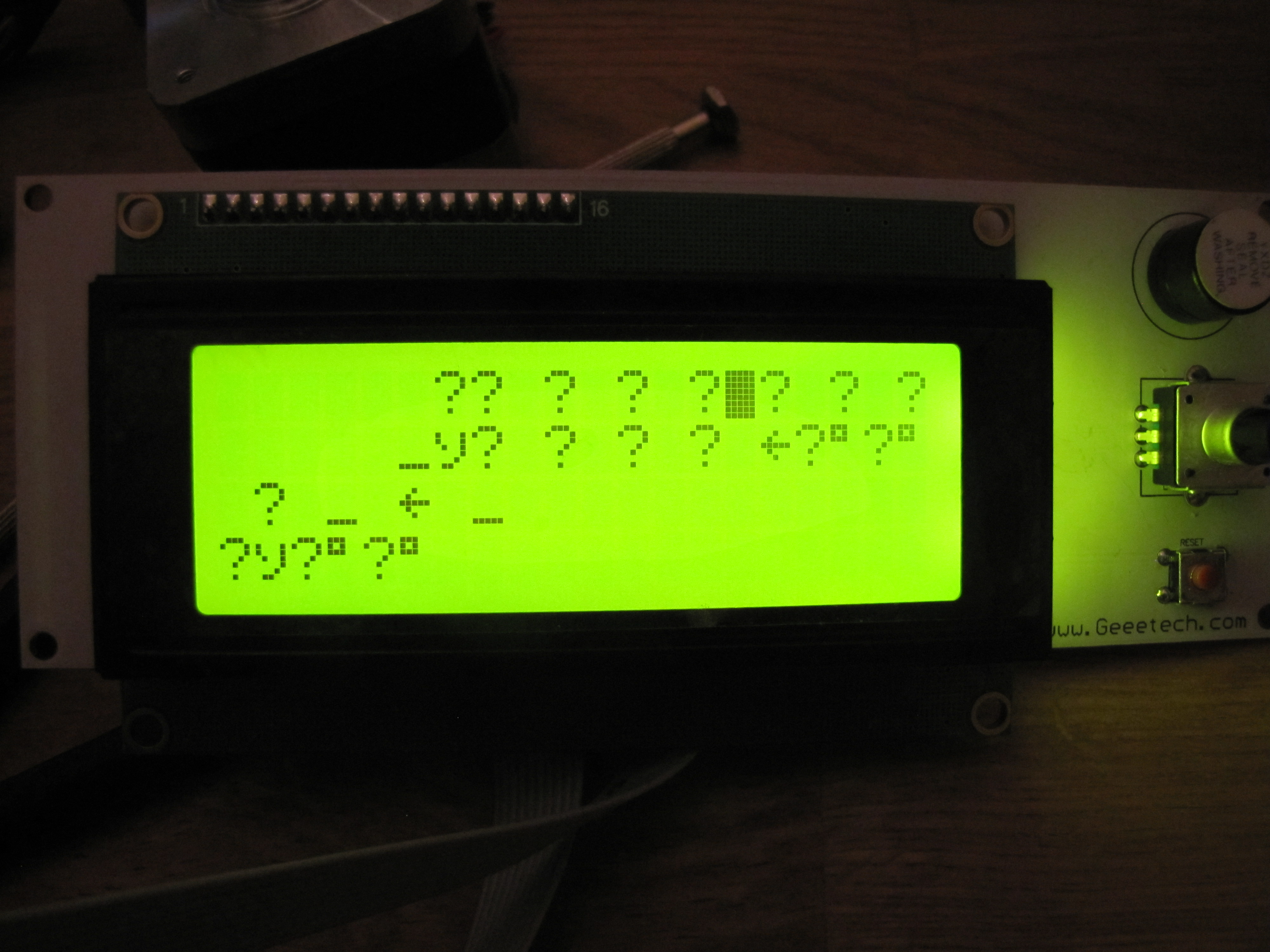
The almighty google suggest multiple possible errors.
First thing to troubleshoot is to see if there is any noticable soldering junk creating crosstalk, I checked both the LCD PCB and Mega2560+RAMPS PCB but I could not find any. I then proceeded to checking the Marlin code to see if I had made any configuration errors.
Unfortunately I had no luck there either.
As a LCD is not required I decided to move on. When the printer is up and running I will probably deal with the LCD errors.
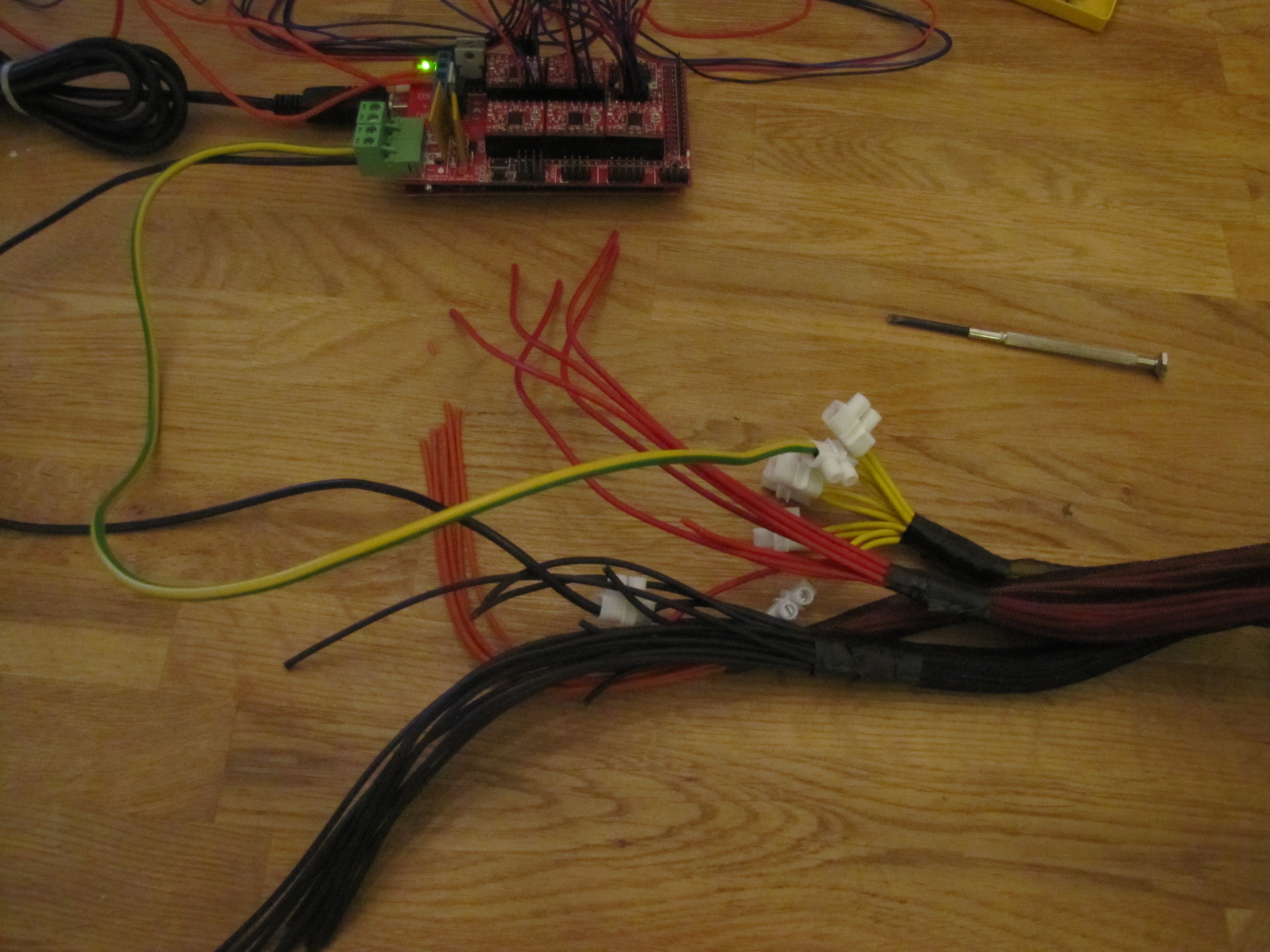
Then I went ahead and configured the endstops. This proved an issue. I’m using 4 pin Mech Endstop v1.2. I had a hard time figuring out which pin did what and after more google I found out more people had made the mistake to wire them wrong and burn the arduino board.
My approach was to connect a LED to the endstop and a tiny bit of voltage from the PSU.
Unfortunately my calculations were off and I managed to burn the fuse on the PSU! 🙁
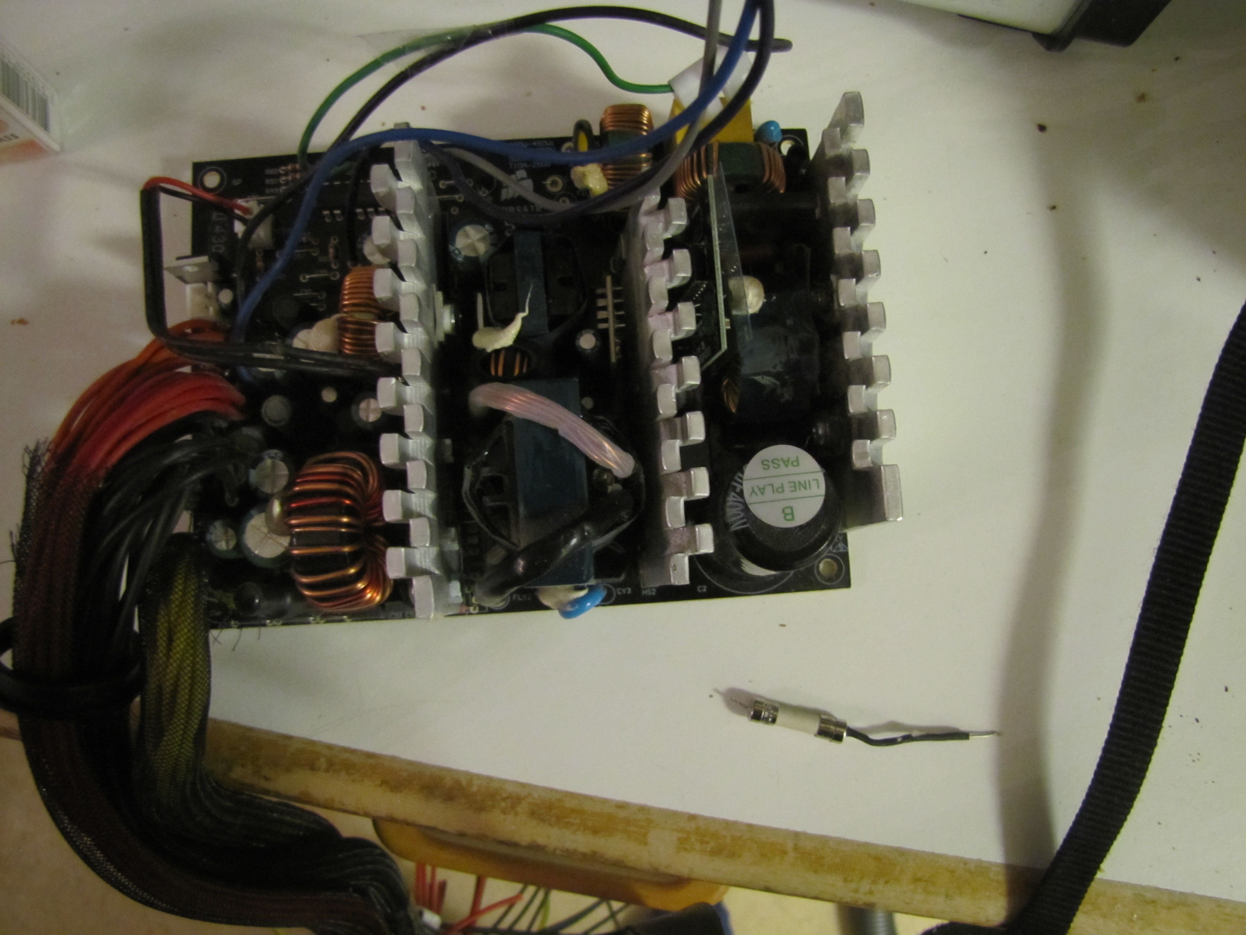
Here is an image of the PSU, next to the big brown cable is the burned fuse.
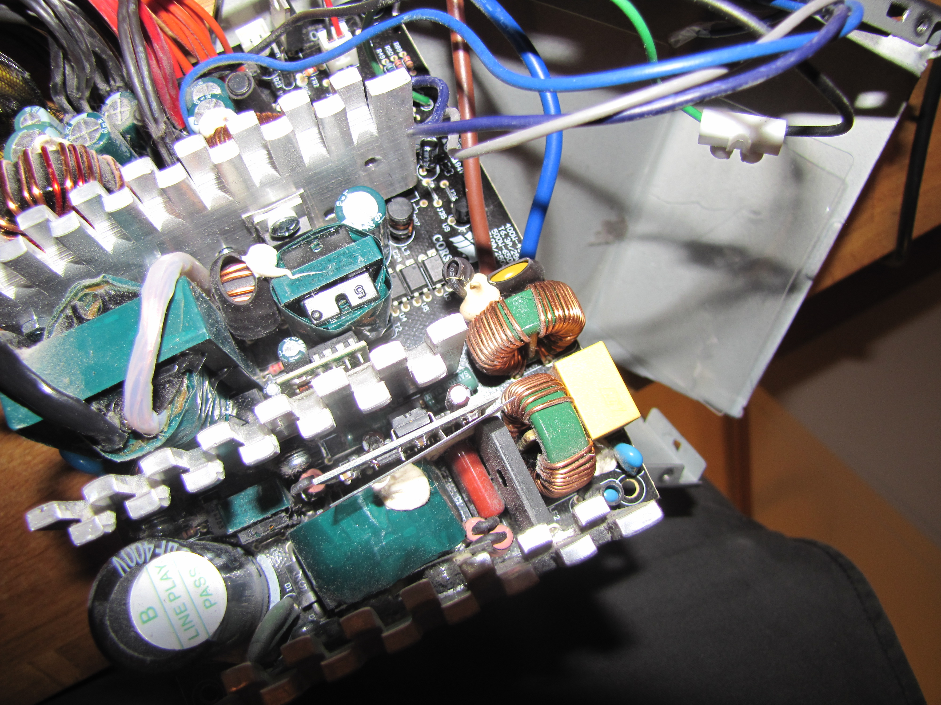
Soldering off the power cords and fuse and from the PSU was easy, however with the PSU built to be compact it was not easy to solder a new 3A fuse.
Here we can see the PSU out of the case with the old fuse on the side.
With the endstop issues solved and PSU works great the main job left is to assemble the printer.
More updates to come!
Ps. More images